Building an Underwater Robotic Observation Vehicle
This project was my final capstone project for my dual degree at the University of West Florida.
We had 2 semesters to complete the project with proper documentation and have a functional prototype.
Our team included 2 mechanical engineering students Brandon and Gabriella.
Starting into our first semester the design ideas flew out fast and we settled on a design that was going to include 3 thruster motors.
This design looked sleek and refined however would require a completly 3d printed shell.
This was going to be a problem, for a few reasons.
1. We did not have a printer large enough.
2. The time it would take to print would not afford us any mistakes.
3. The space inside was too small.
Thus, our next design.
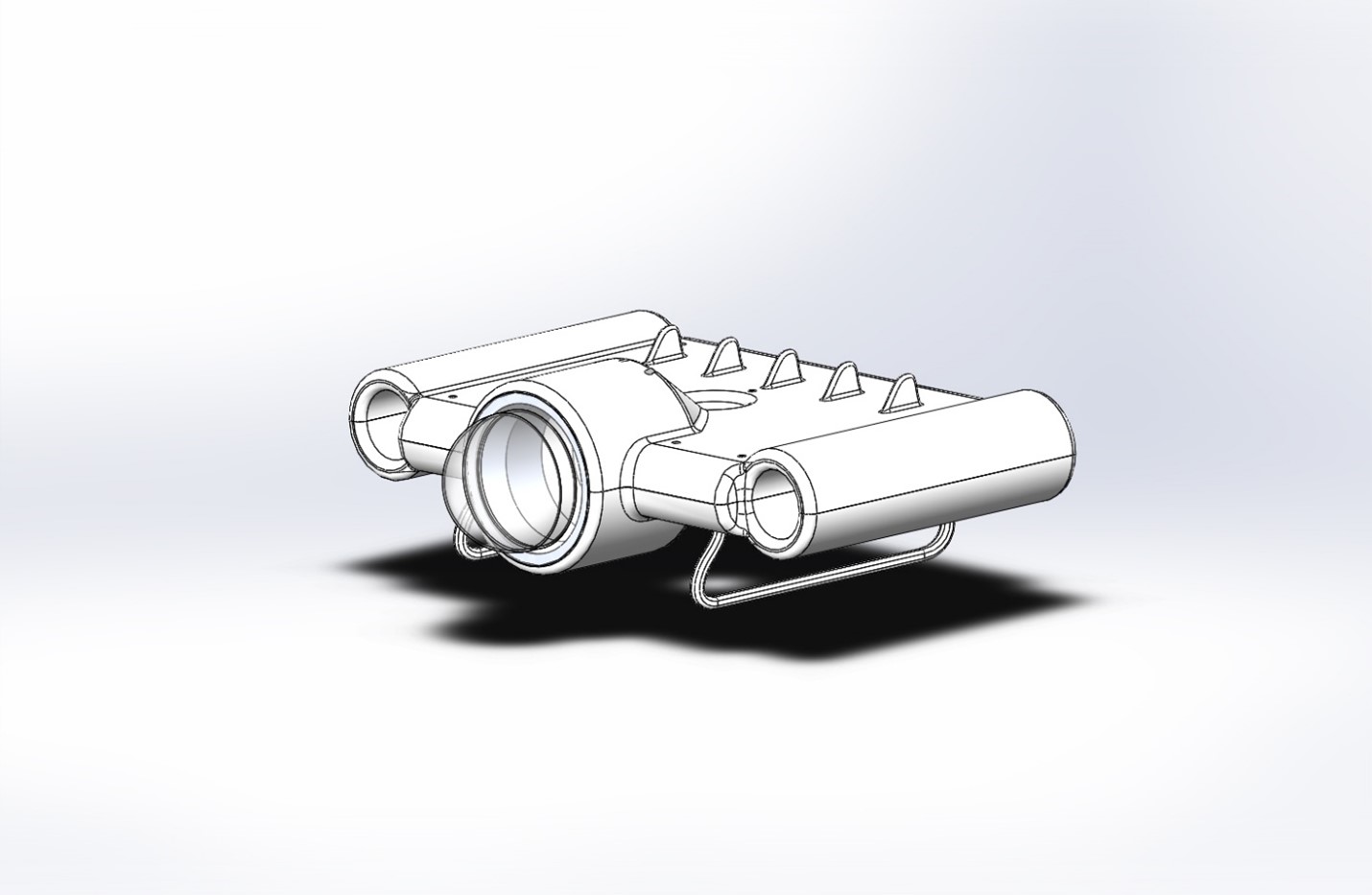
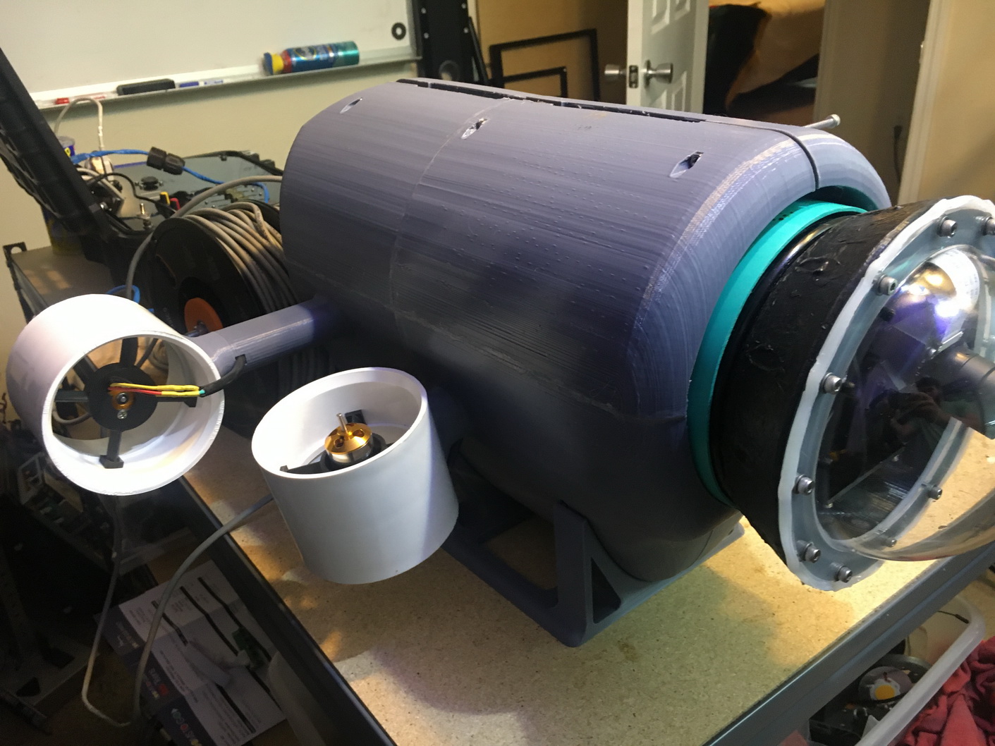
The new design allowed a 3D Printed shell to be made in two halves and the thrusters could be attached externally. A PVC pipe would be used for the interior tube to contain the electronics.
This would help to ensure the ROV was airtight.
The new design was modeled in CAD and work began on the electronics.
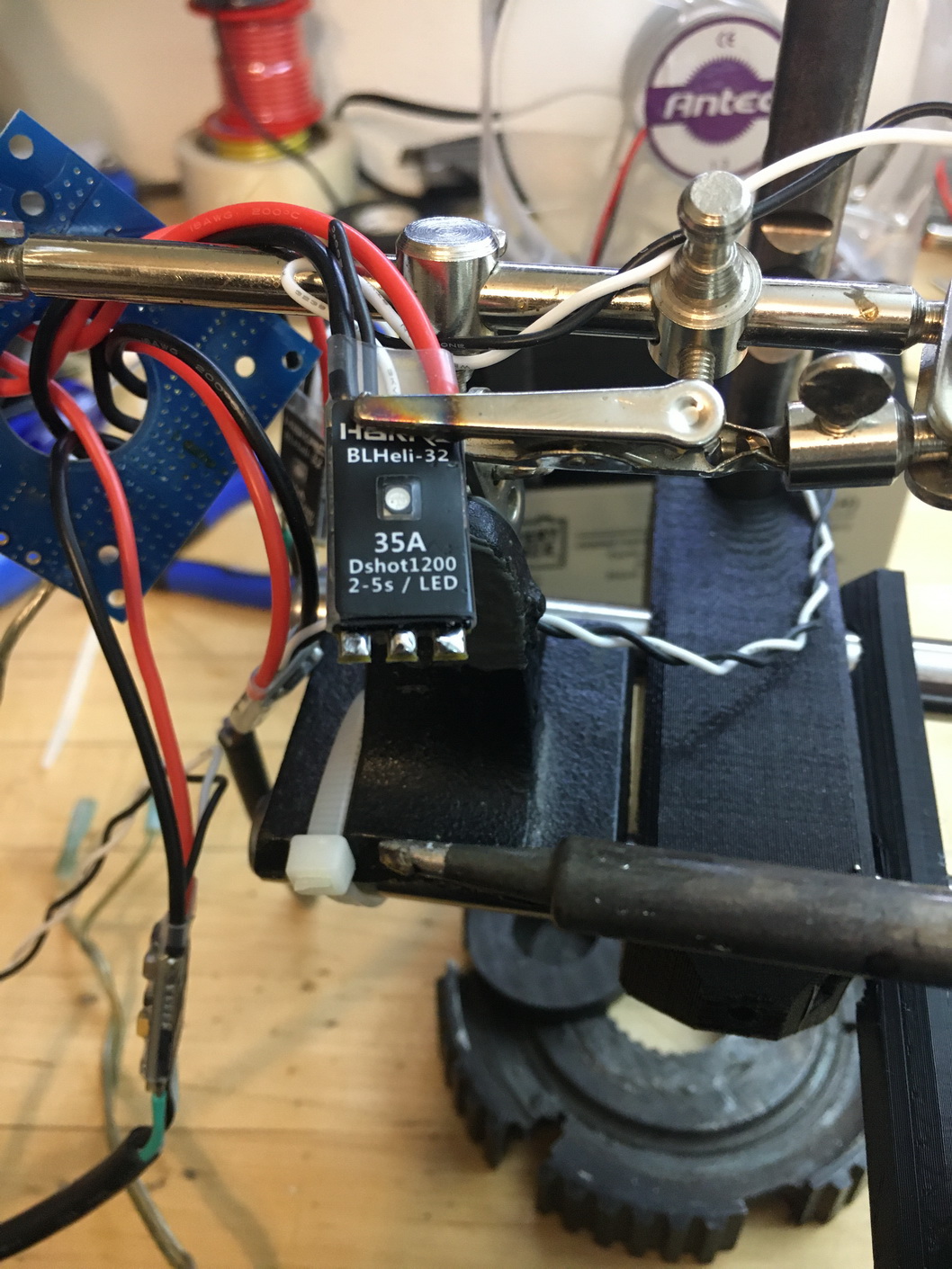
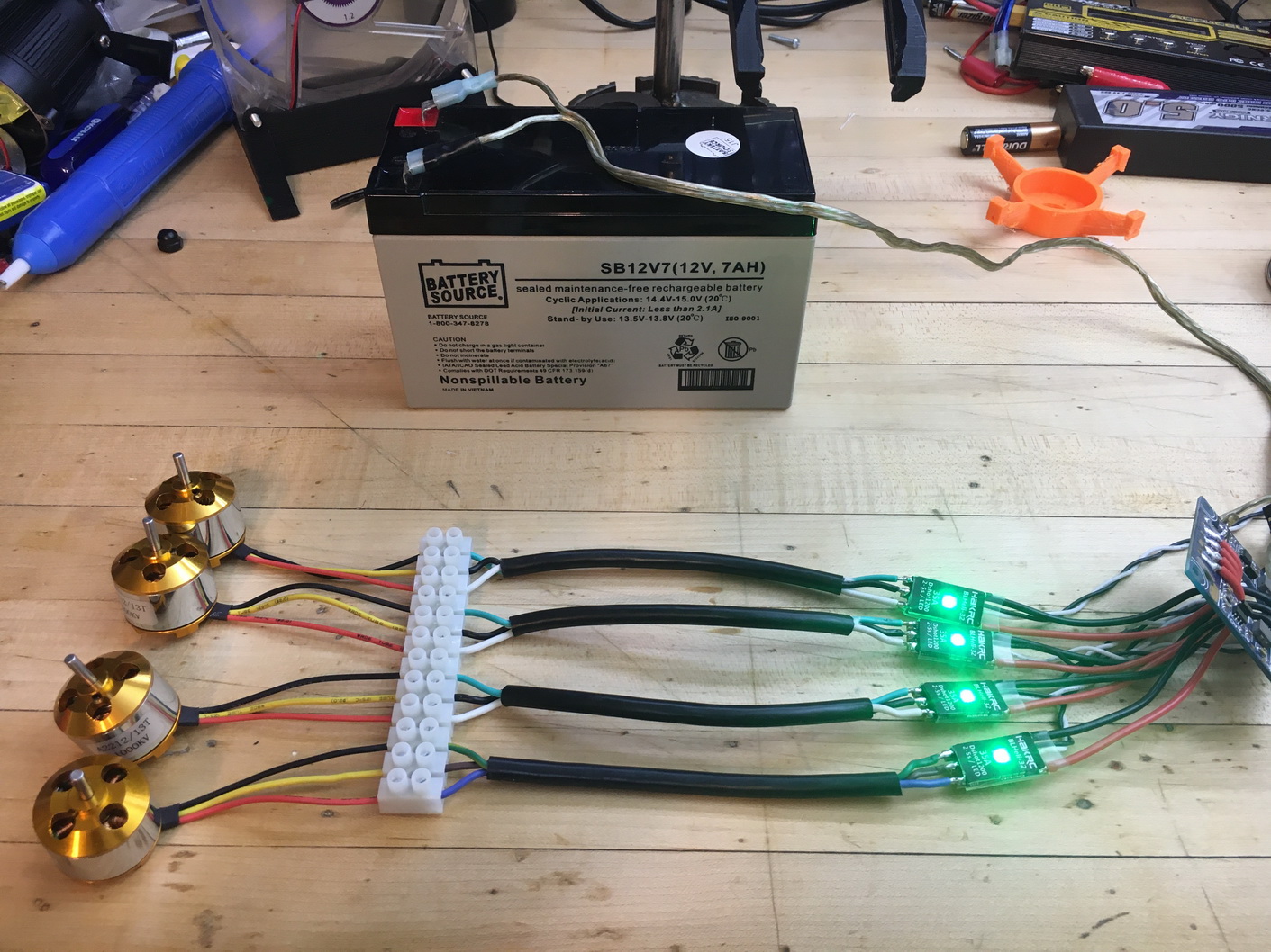
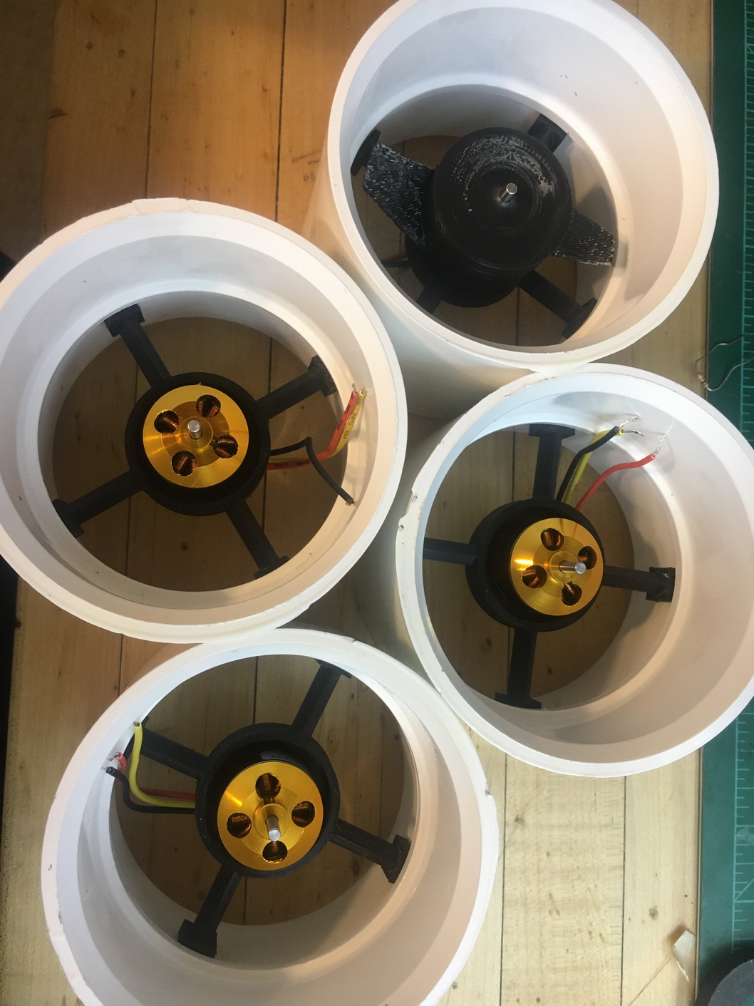
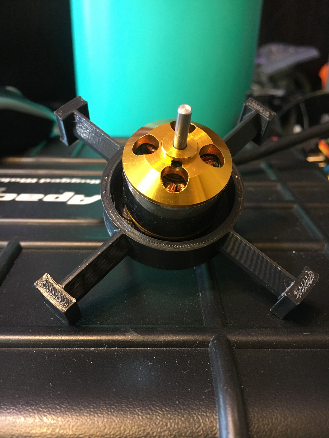
Motors and ESC's were ordered as well as the camera module and stepper motors.
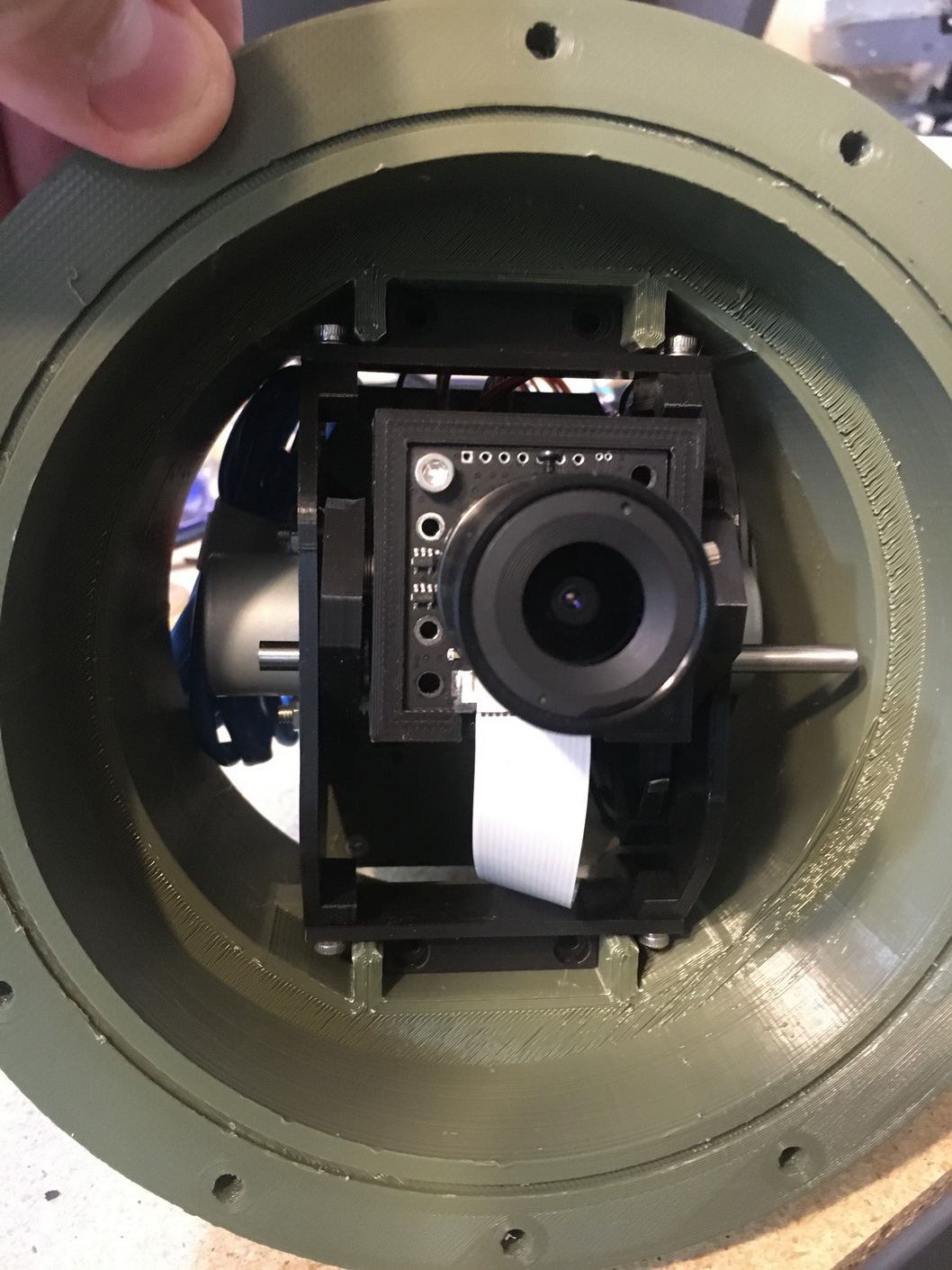
The camera module tilt mechanism was designed in CAD, 3D Printed and assembled.
Functional testing started with the rs232 modules to get two arduino modules to transmit and receive data.
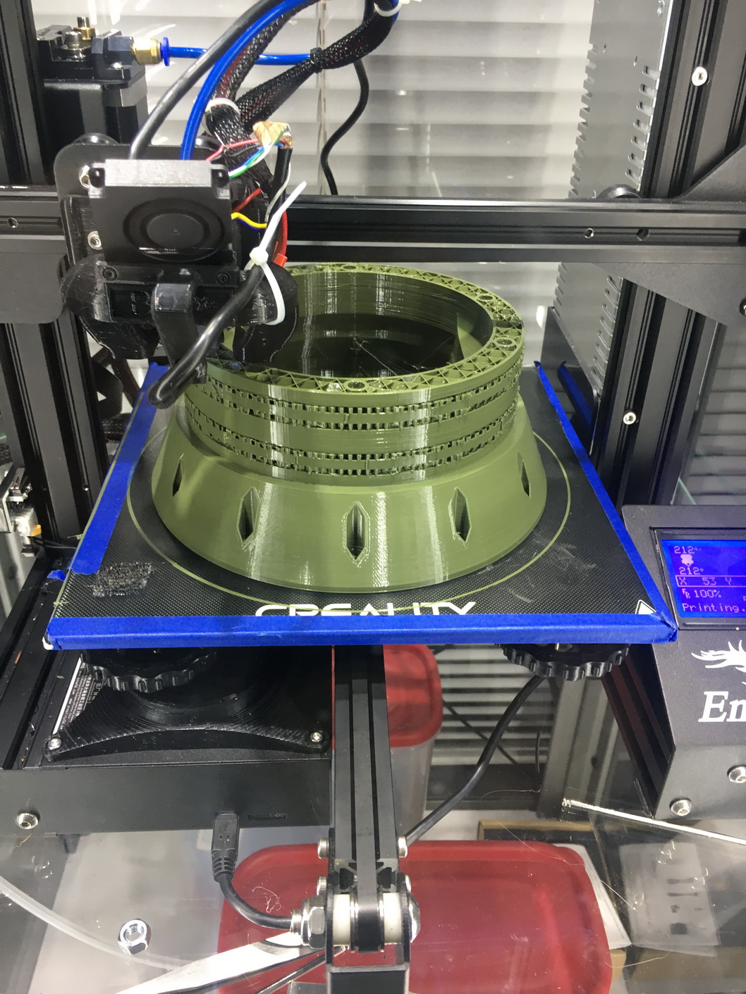
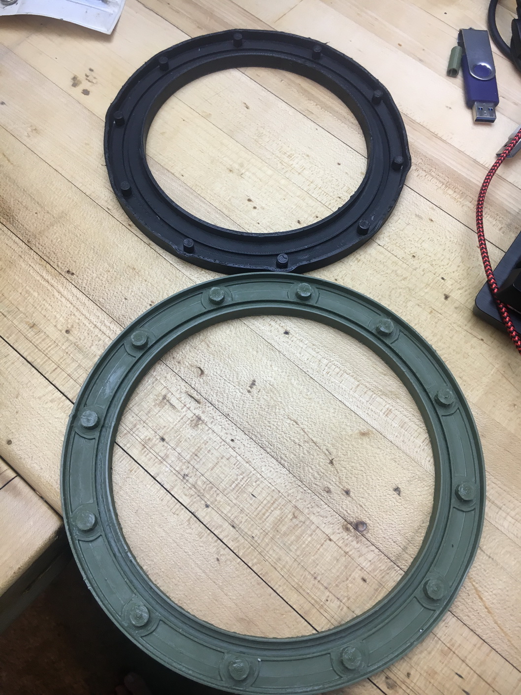
The front Flange was 3D Printed.
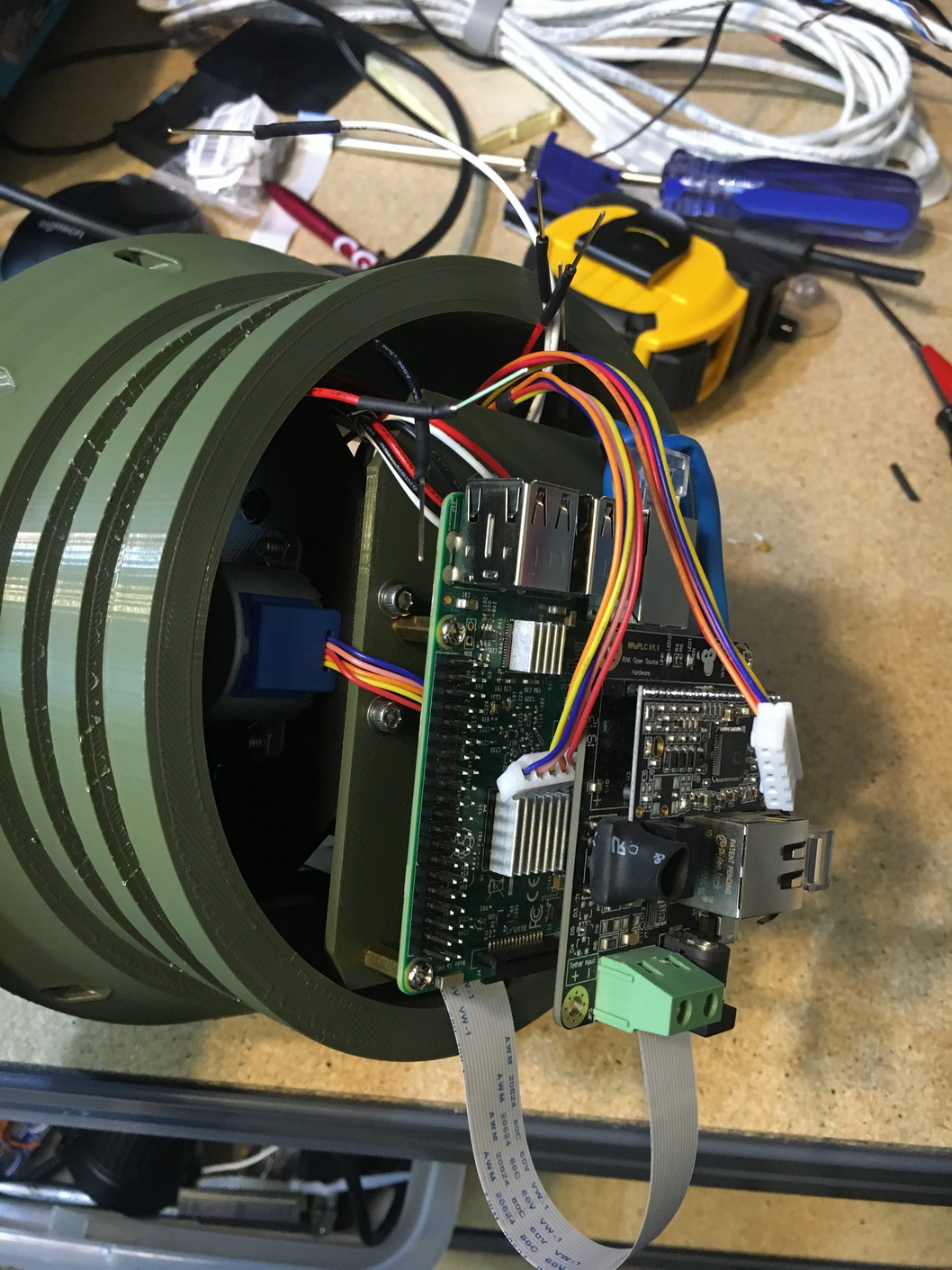
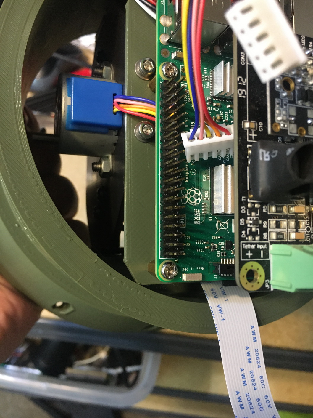
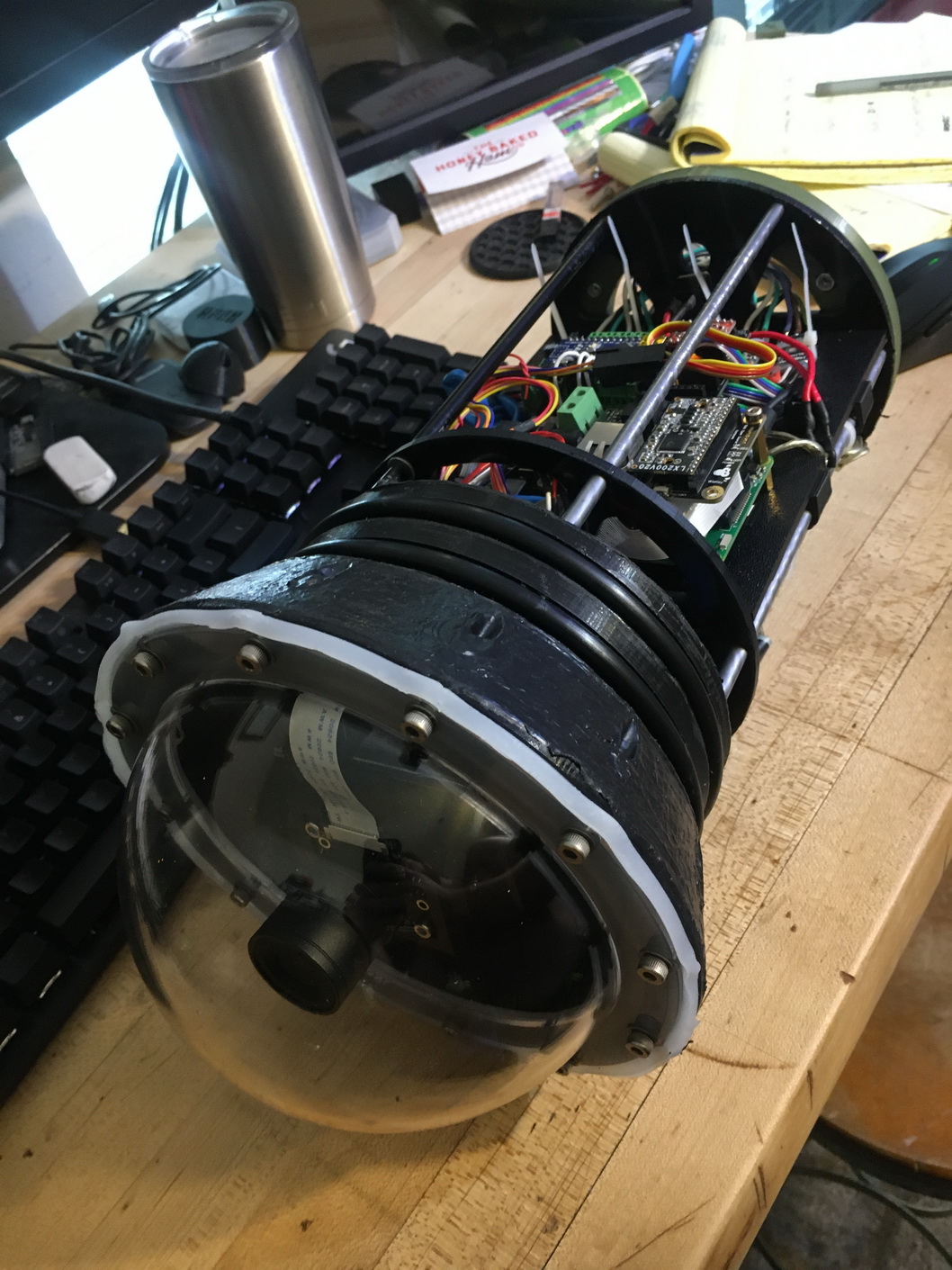
The camera module was installed. The Raspberry Pi was mounted and tested for camera functionality.
The motor mounts were 3D printed and a 5 minute epoxy was used to secure the frame to a PVC coupler for the shroud.
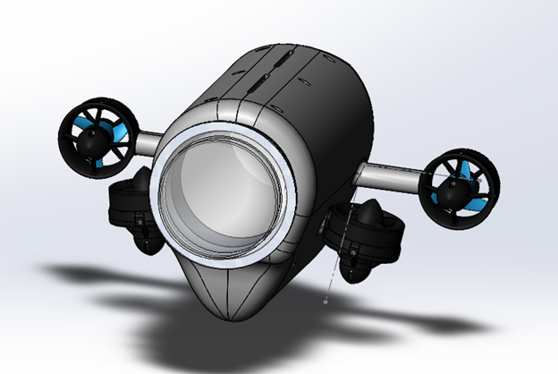
The front camera dome was ordered and fitted. The scale of the flange was off by 2% so the dome did not fit.
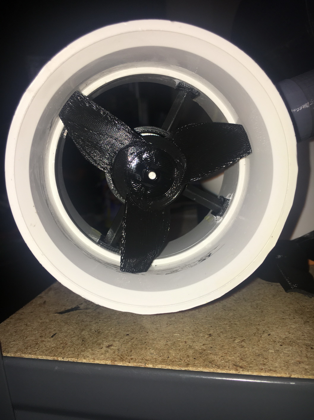
I tried my hand at designing some custom propellors for the thrusters as well
The pitch was to too steep for the output torque of the motors under water. In air they worked amazing.
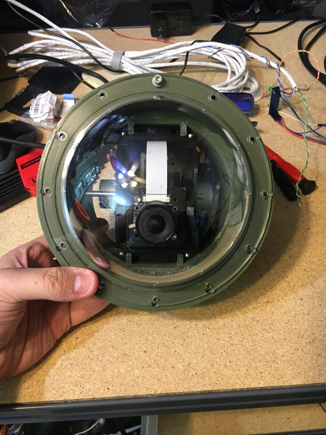
A new flange was printed.
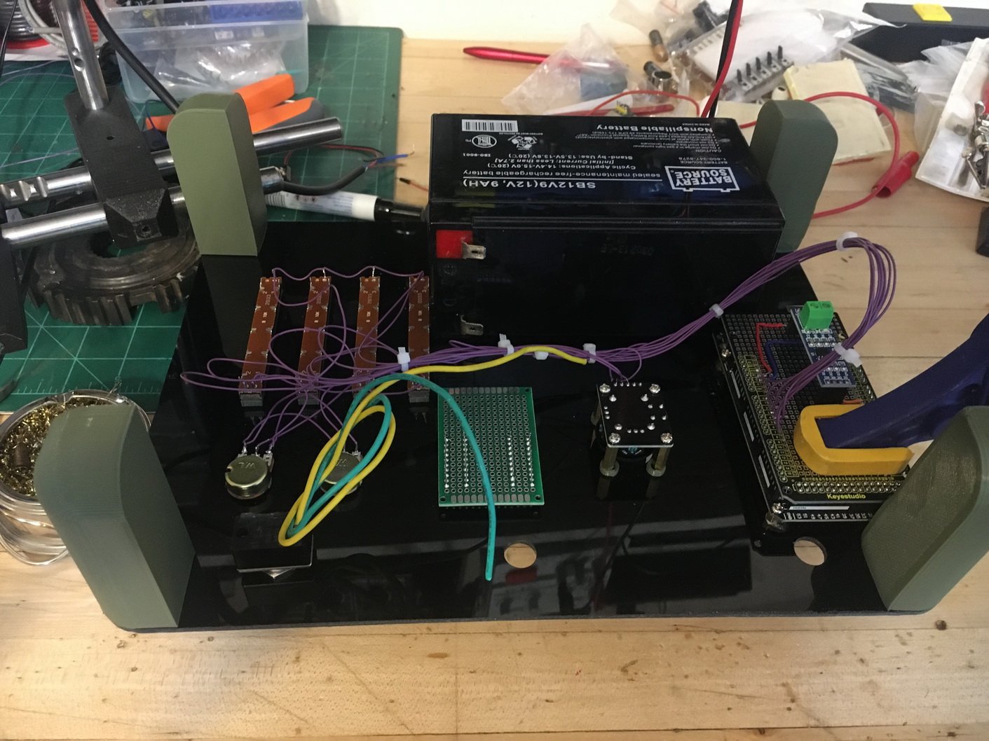
Electronics Design
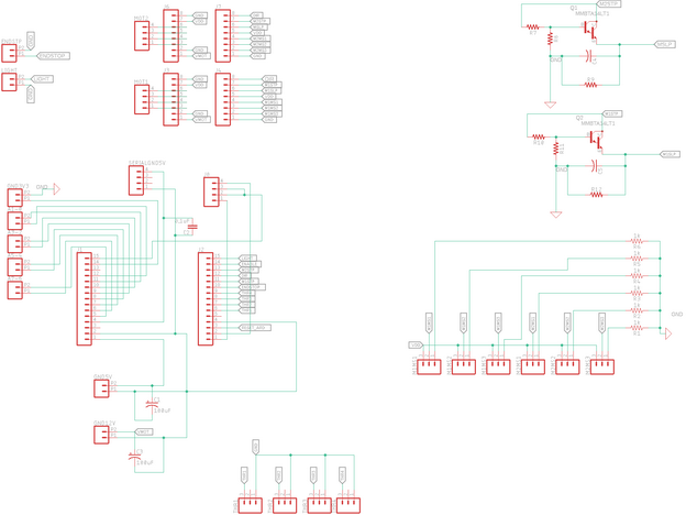
I designed a Darlington pair transistor charge pump that was used to reduce the number of channels needed to control the camera gimbal motors.
I used ON Semiconductor MMBTA14LT1G NPN Darlington Pair Transistors and some generic A4988 stepper motor drivers that required a PWM input, an enable pin and a direction pin.
I wanted to utilize the enable and sleep pins to save on power while the camera was idle.
The intention was to use the pwm step signal to charge an enable pin reducing the step and enable to a single output. The capacitor would dissapate the charge in about 10 seconds.
Once it was installed the circuit functioned perfectly. The capacitor would charge quickly and the camera would move. Soon after the joystick was released the driver would shut off.
Functionality for LED and IR lights as well as a depth sensor were added in the schematic as well.
A TE connectivity MS5837-30BA was selected for depth sensing. It is capable of 0.2 cm resolution in water and has a pressure range of 0 to 30bar.
The depth sensor also uses and I^2c interface which is nice
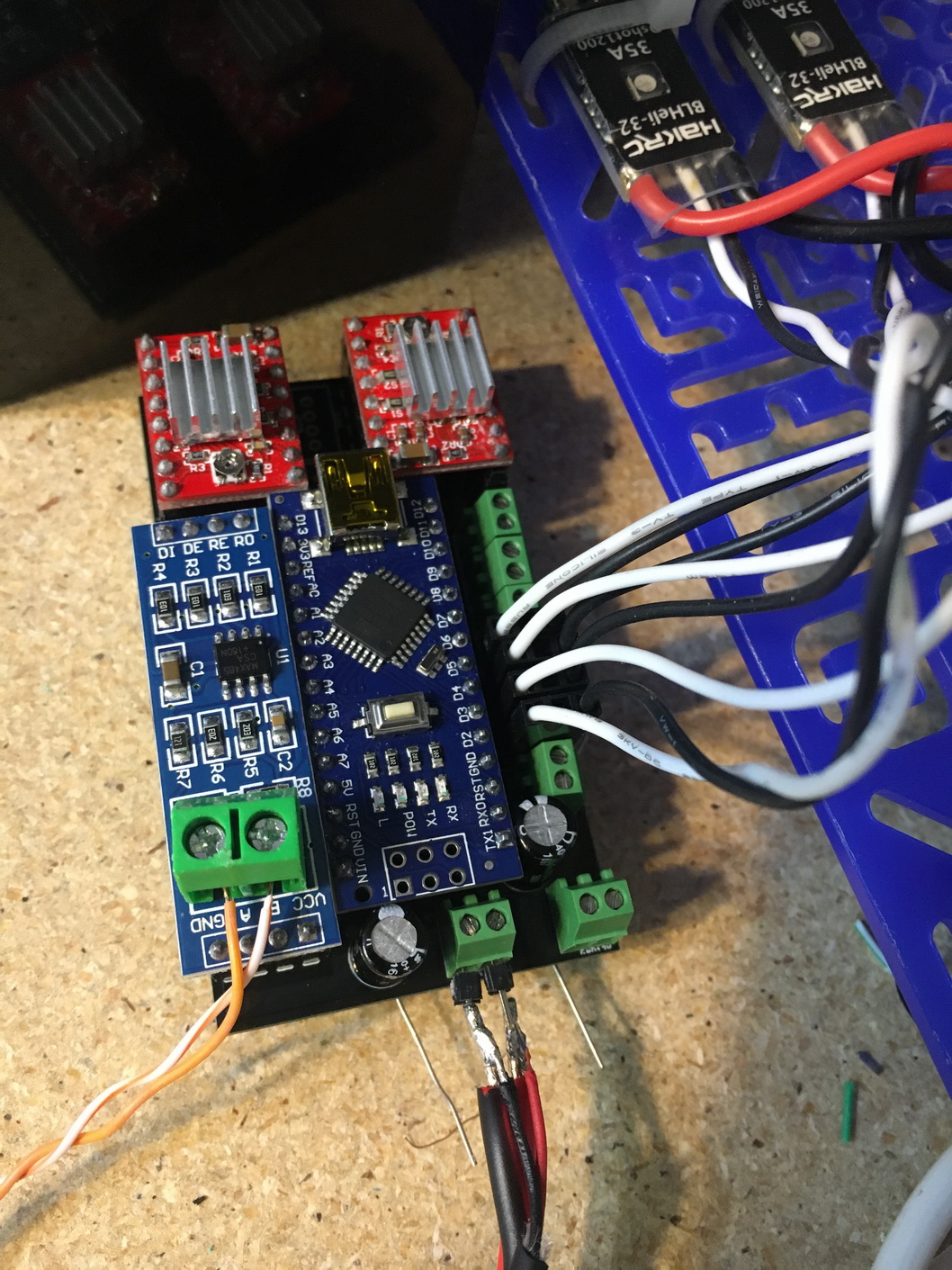
A MAX485 chip was used to provide the 2 wire RS232 interface. A generic board was purchased and installed
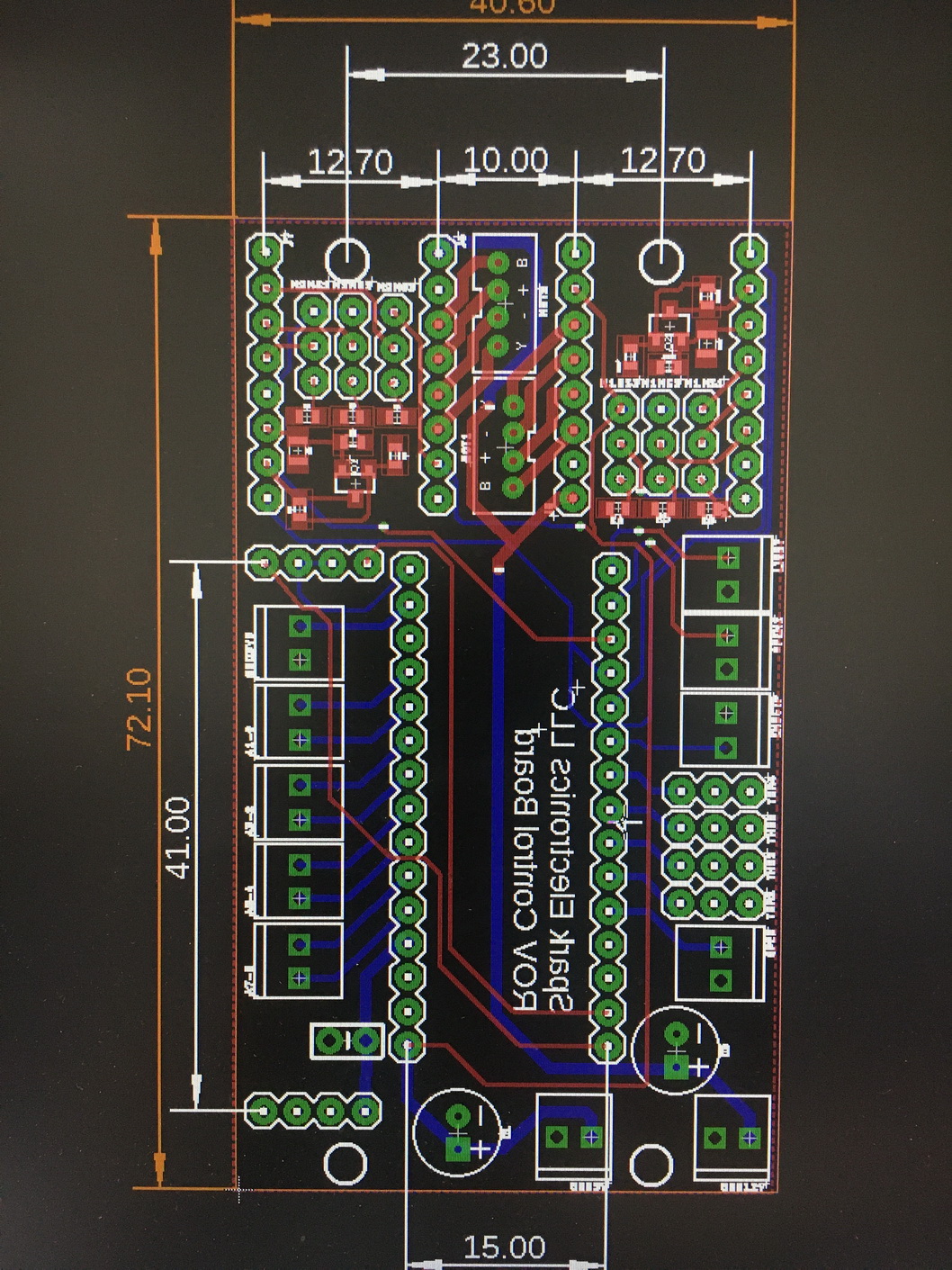
Once the electronics were tested and everything functioned properly, a schematic and board were designed. I ordered the PCBs from purple PCB.
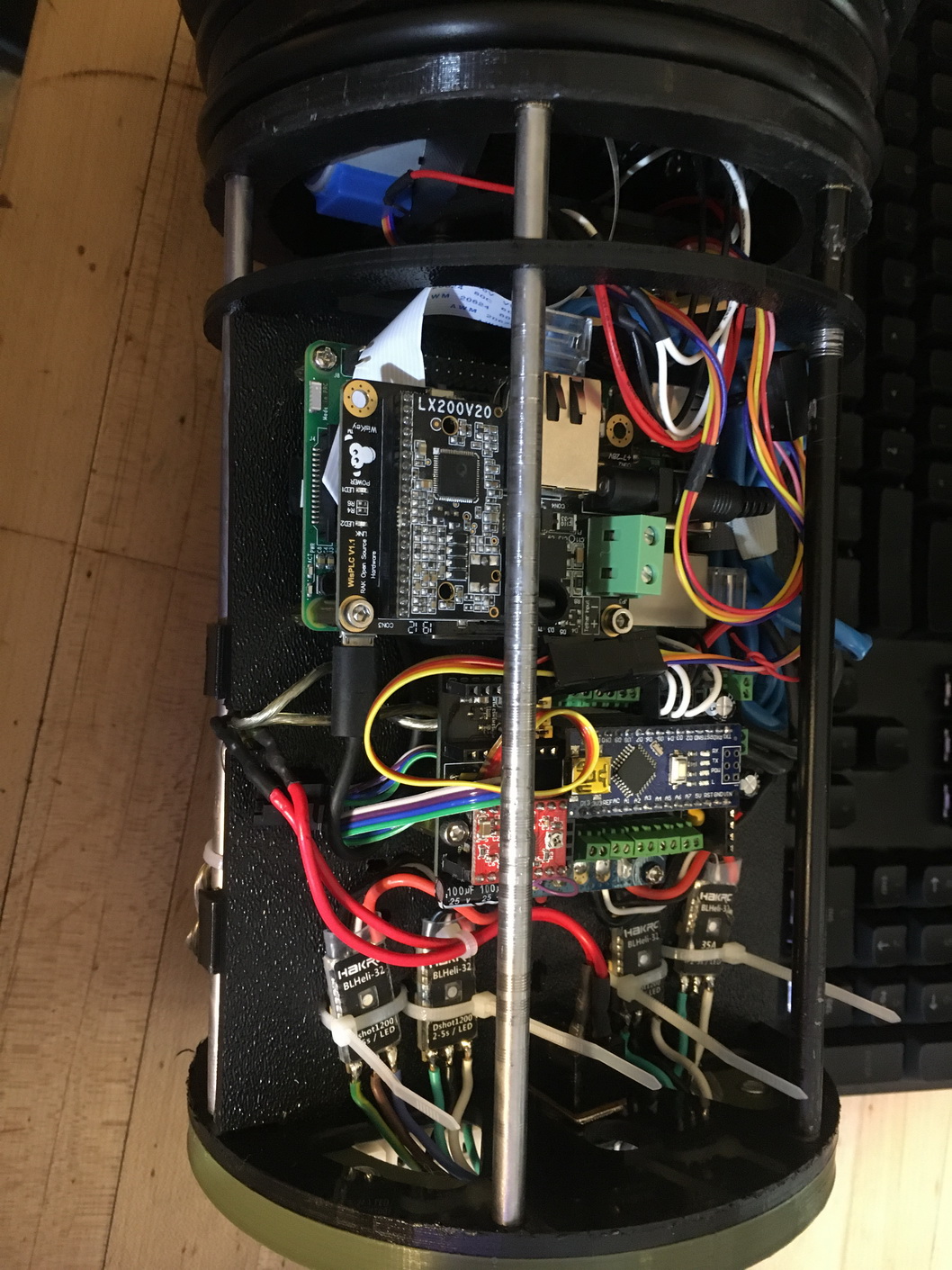
An arduino nano was used to control the ROV
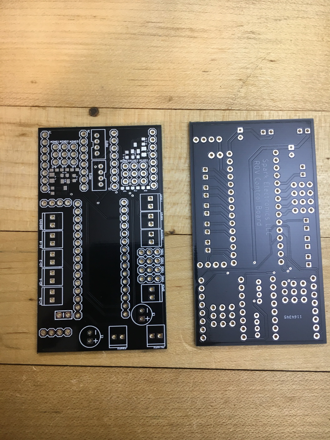
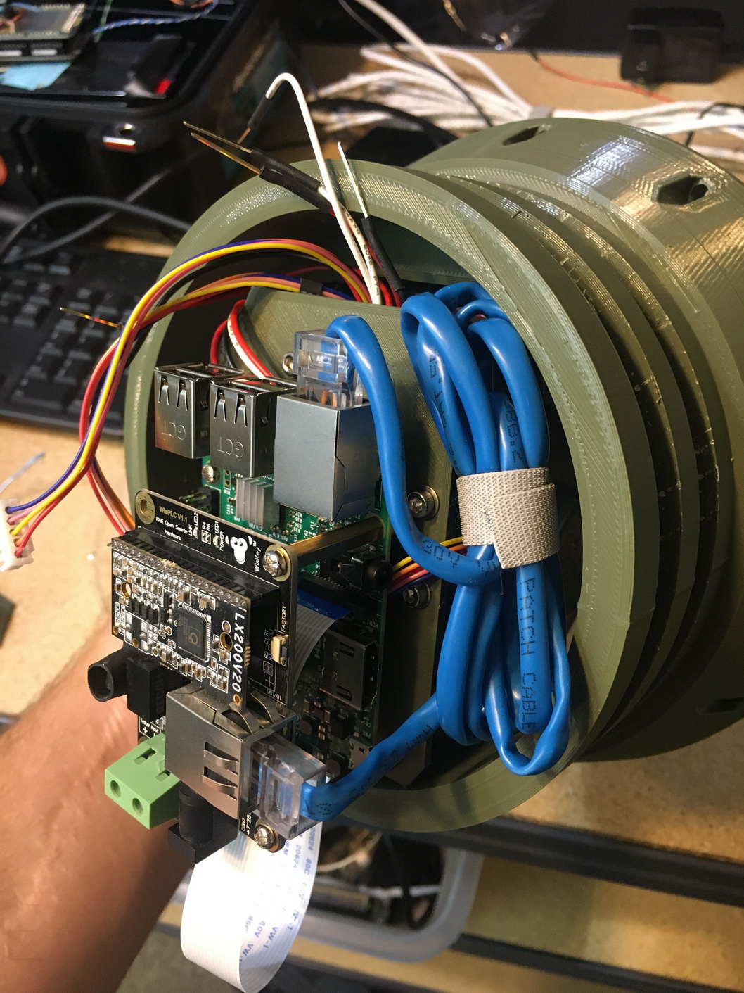
A RAK Wireless WisLink LX200V20 EVB was used to stream the camera feed from the onboard raspberry pi to the control center over a 2 wire rs485
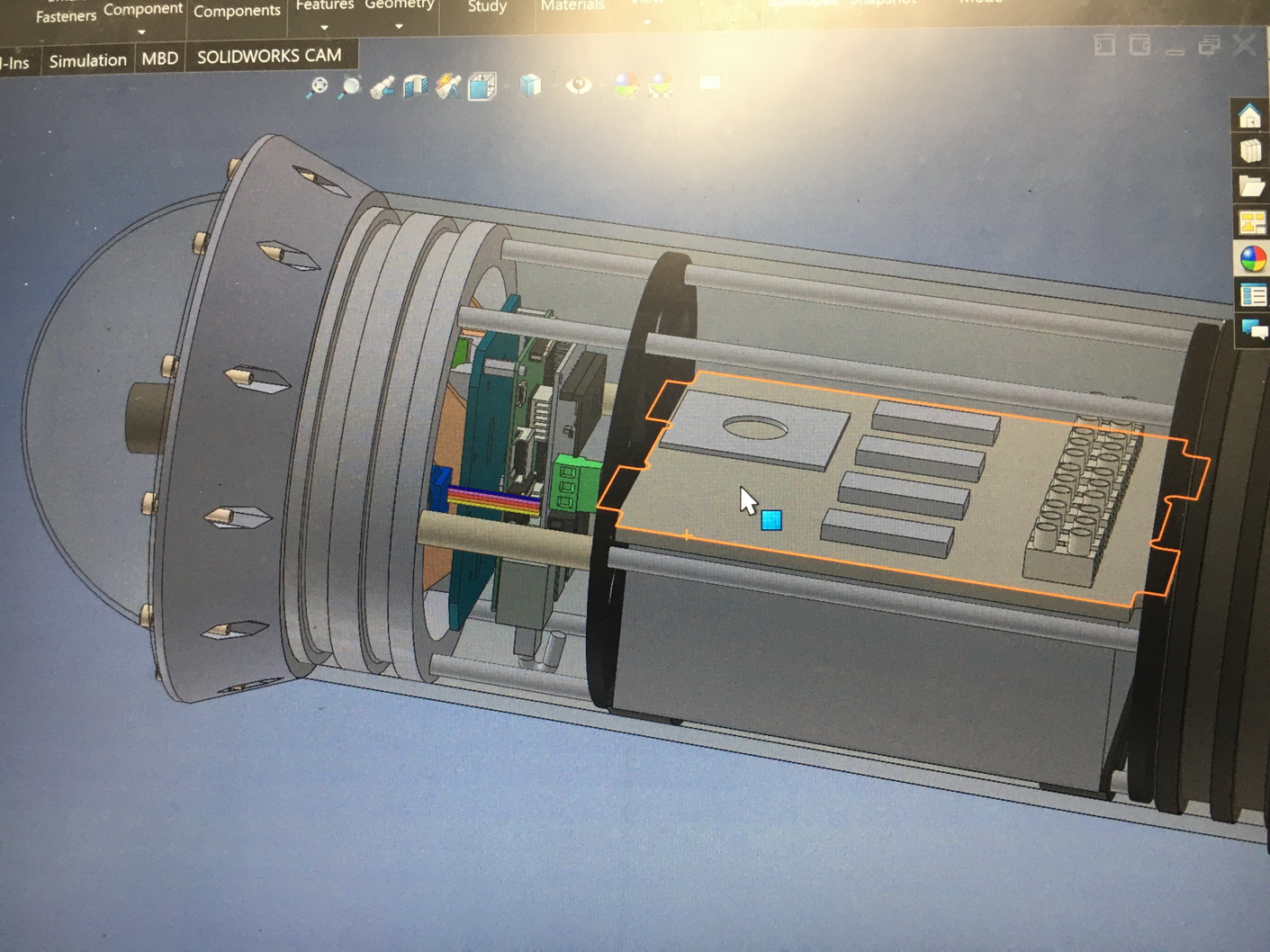
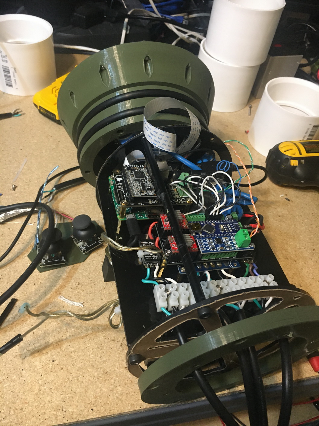
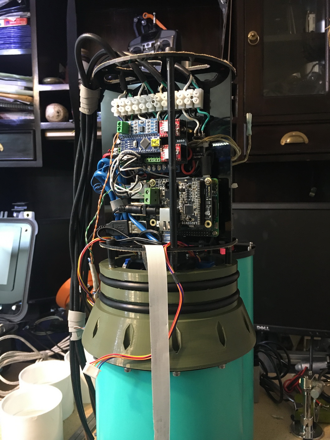
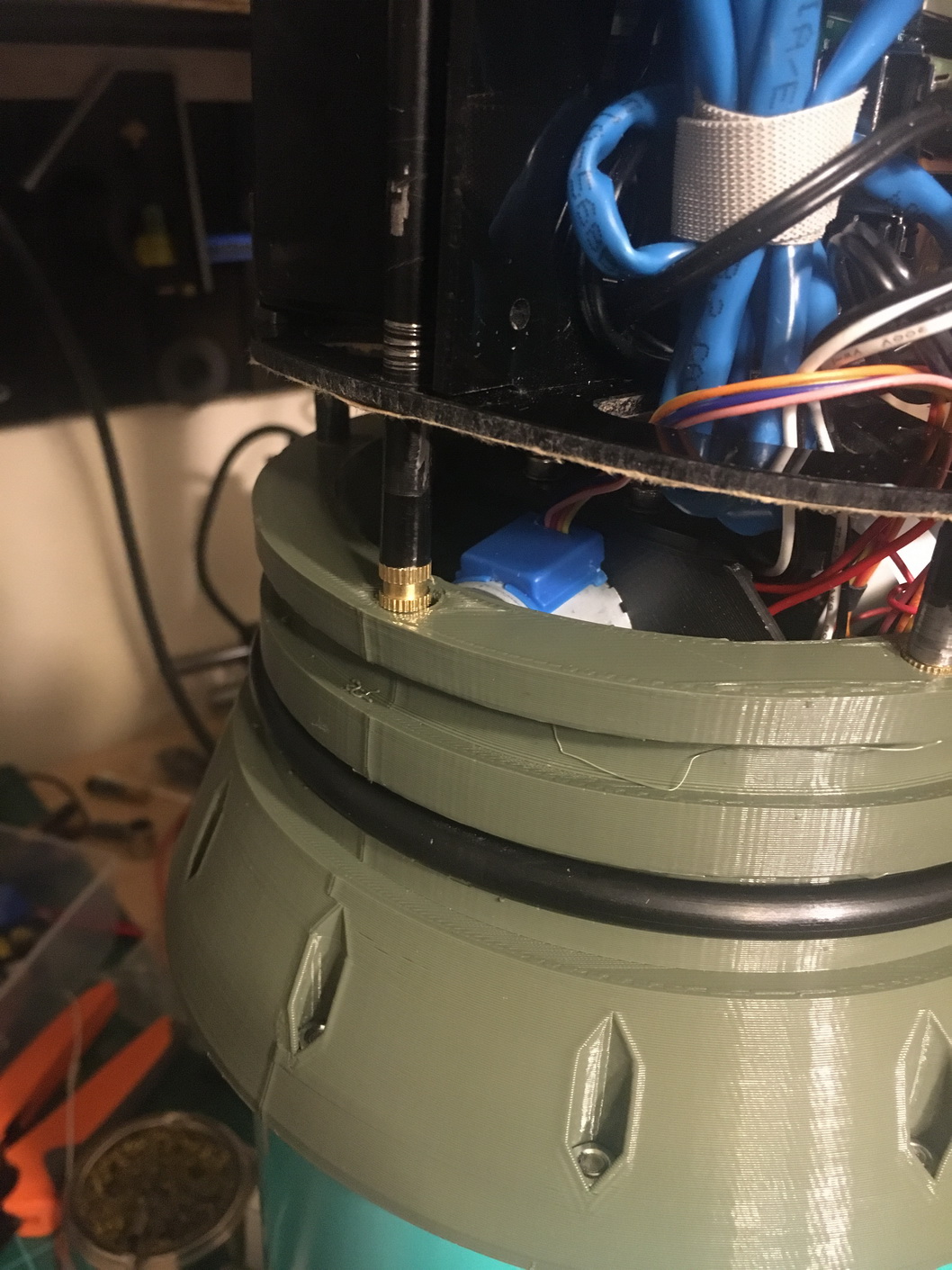
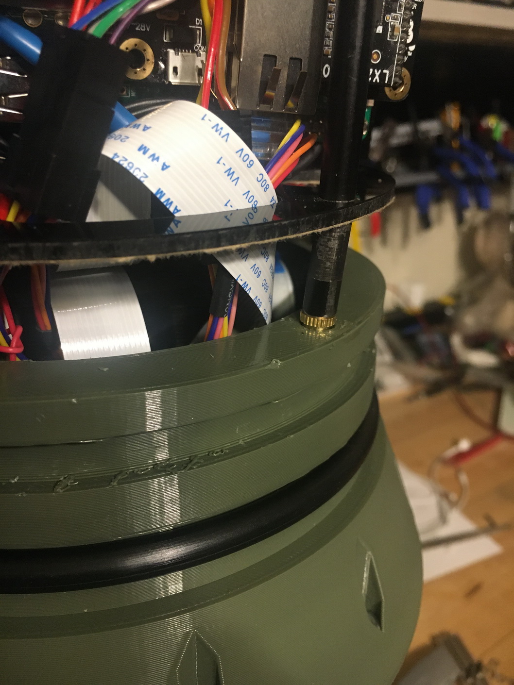
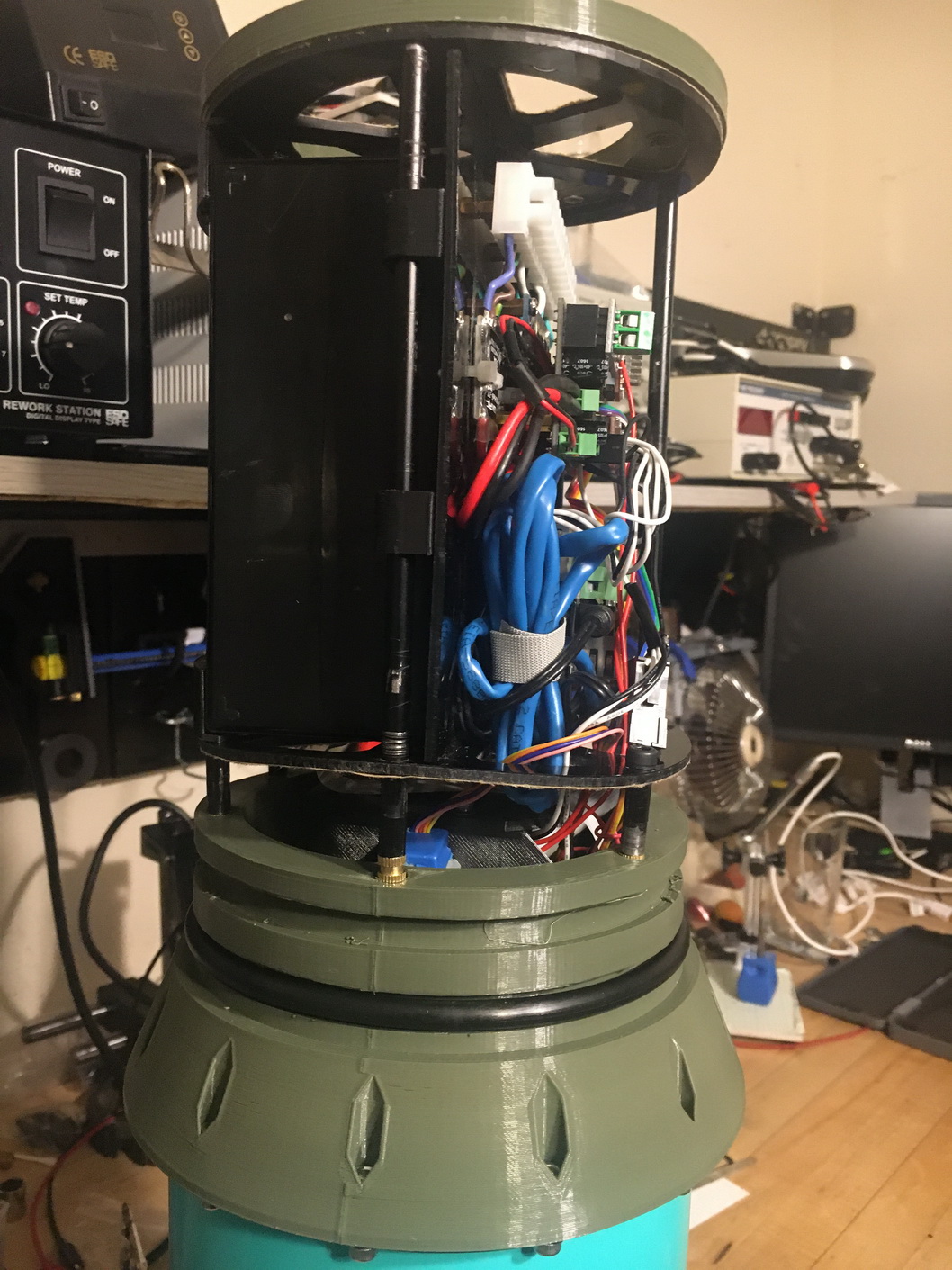
The internal frame assembly started.
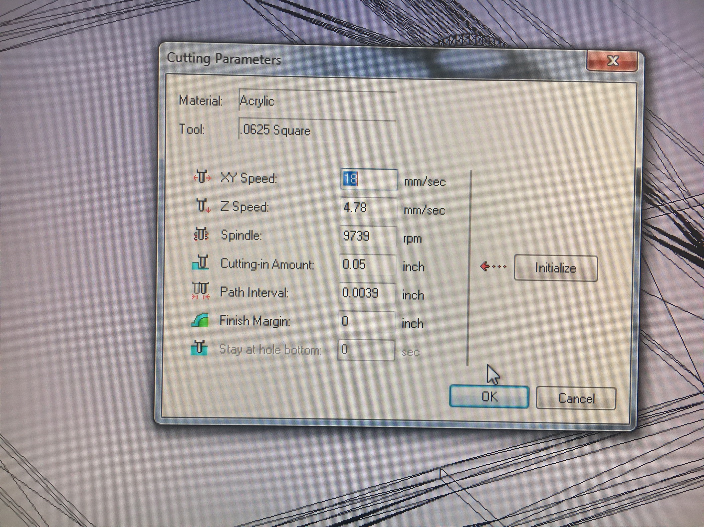
All of the internal plastic pieces were milled out of ABS sheets.
Brass heat set inserts were used to attach the electronics frames to the front flange.
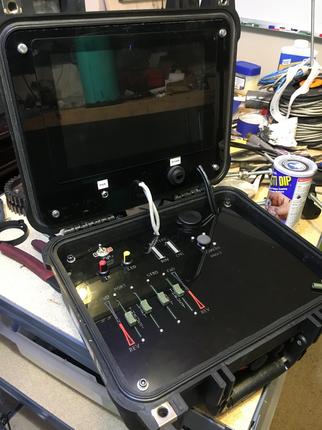
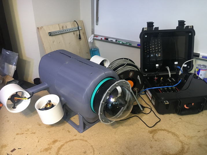
Once the interals were functioning properly design of the control station started.
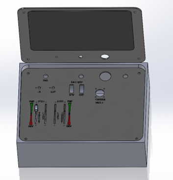
I wanted to use a raspberry pi and a large screen. I ordered a generic 10 inch HDMI touchscreen.
The Raspberry pi was mounted on the back of the display so I needed to get USB for serial data to the arduino microcontroller into the bottom panel.
I used a generic usb panel mount receptacle and ran the wires through the top and bottom panels.
Potentiometers were added to control lights both IR and LED
Battery indicators for the control panel and ROV were added
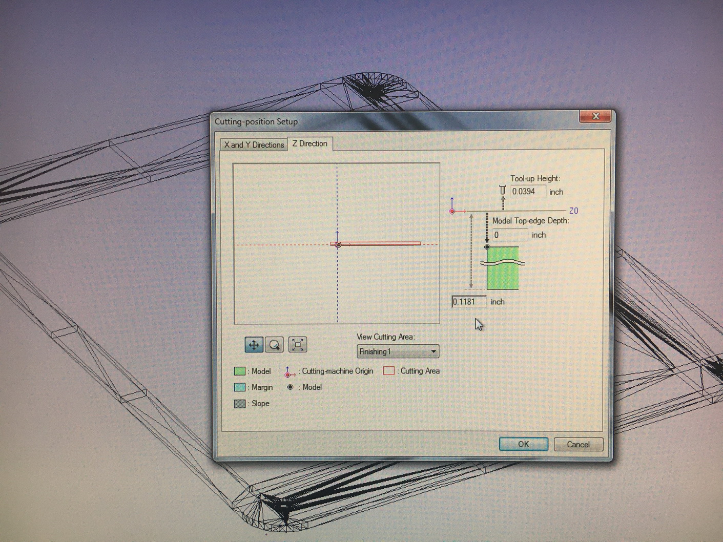
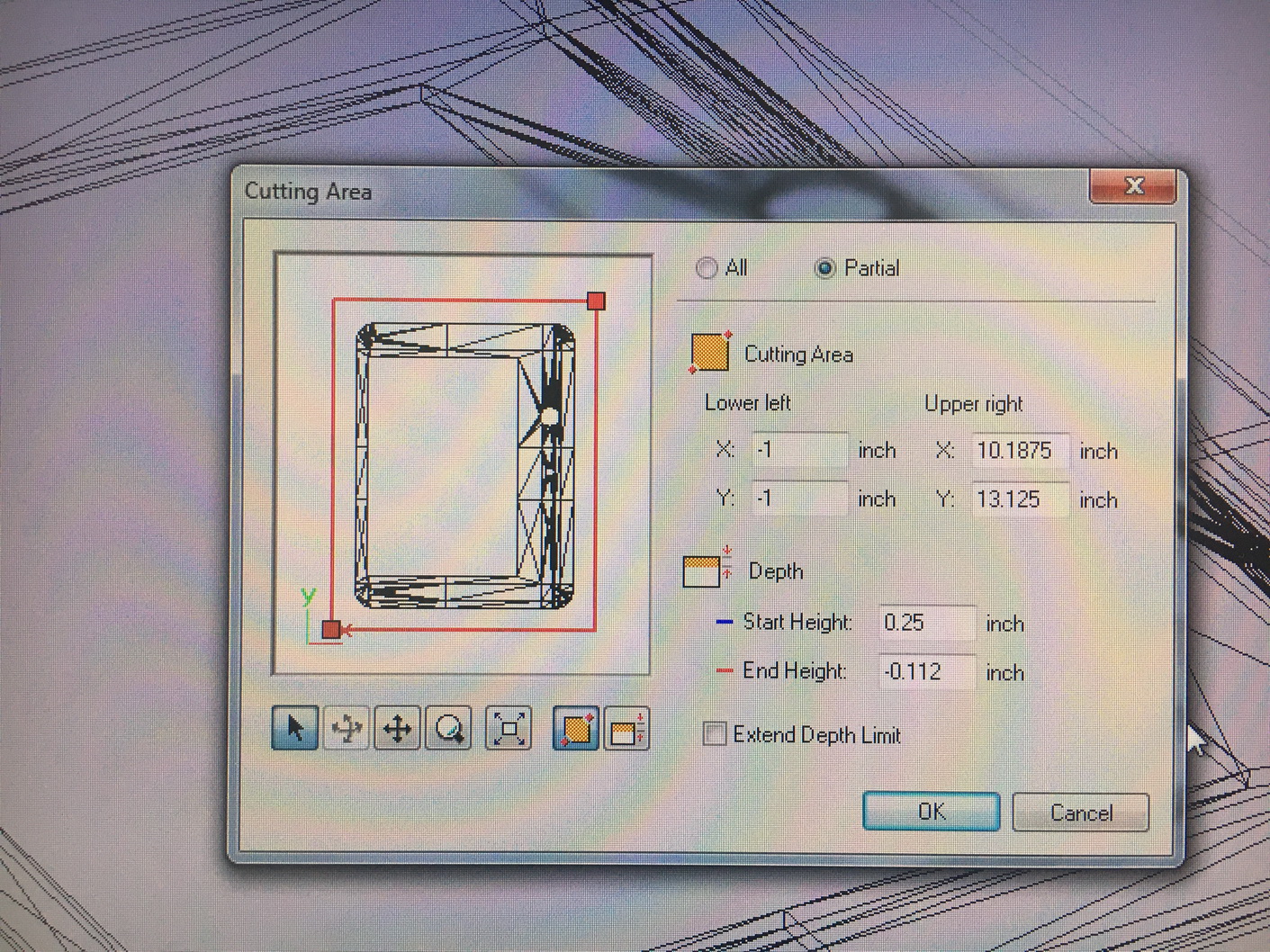
The panels were exported and milled using a CNC router.
The case was then assembled and testing began.
I used 4 Bourns 60MM 10K linear potentiometers for the controls of the thrusters. They were small, precise and easy to use.
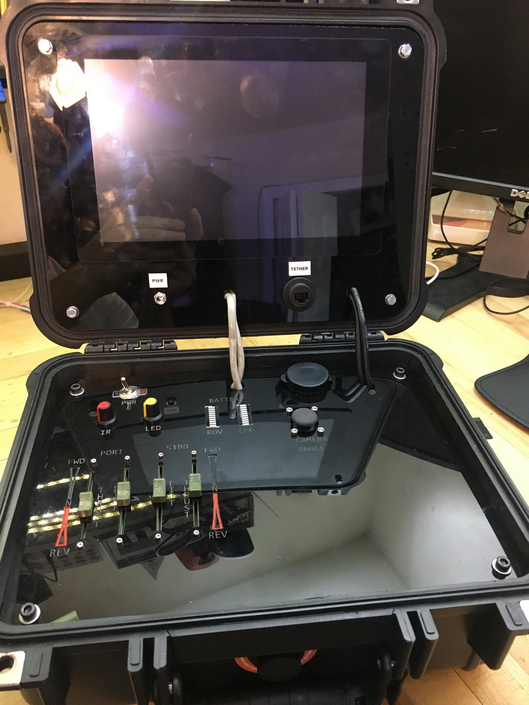
The case was wired and tested.
A program to control and display the camera feed and UROV status remotely was started. A C# program was written with a windows forms GUI.
Python was used to display camera feed
mono was installed on the raspian IOS to support .net framework.
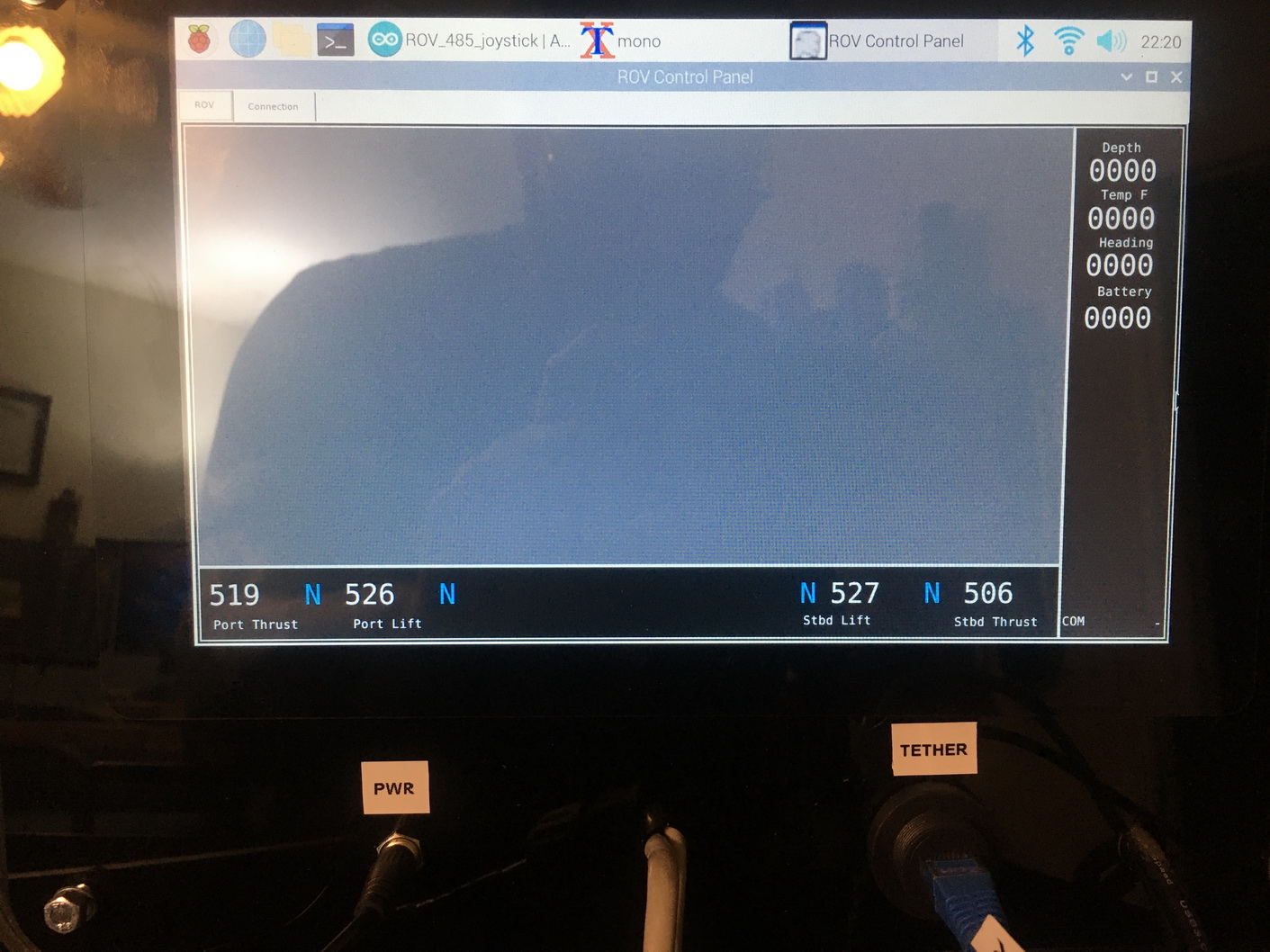
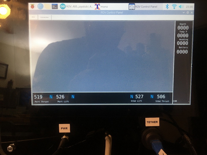
The program would display a value of (-512 -0- 512) for the thrusters beacuse of the 8 bit adc on the Arduino.
A N was dispalyed for the range near center for neutral.
A F was displayed for forward movement and a R was displayed for reverse movement.
Time for Assembly
With most of the electronics finished and the flanges printed and assembled, a leak test was performed.
Apparantly 3D printed plastic is not water tight.
A new flange was printed with 80% infill.
It was still leaking.
A new flange was printed with 100% infill.
It still Leaked
I coated the inside of the flange with marine epoxy.
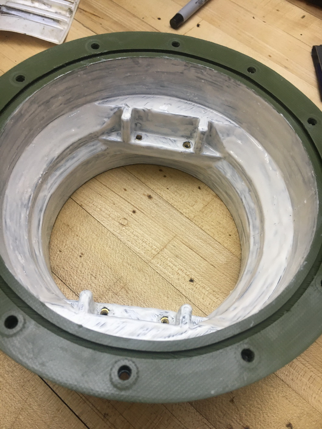
It still Leaked
I pulled a vacuum on the assembled shell and painted the outside of the flange with a rubberized coating.
This fixed the leaks in the flange body.
The front where the clear bubble dome was connected needed a seal
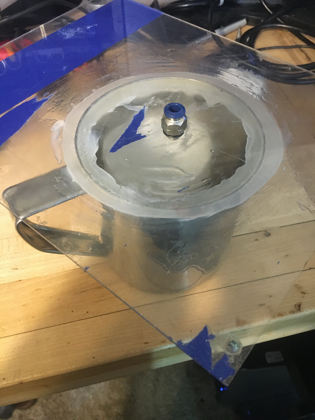
I 3D printed a mold to create the silicone gasket.
I made a makeshift vacuum degass chamber and diluted some silicone using naptha and added cornstarch.
The first gasket did not release from the mold.
I should have used mold release.
I put petroleum jelly in the mold and tried again.
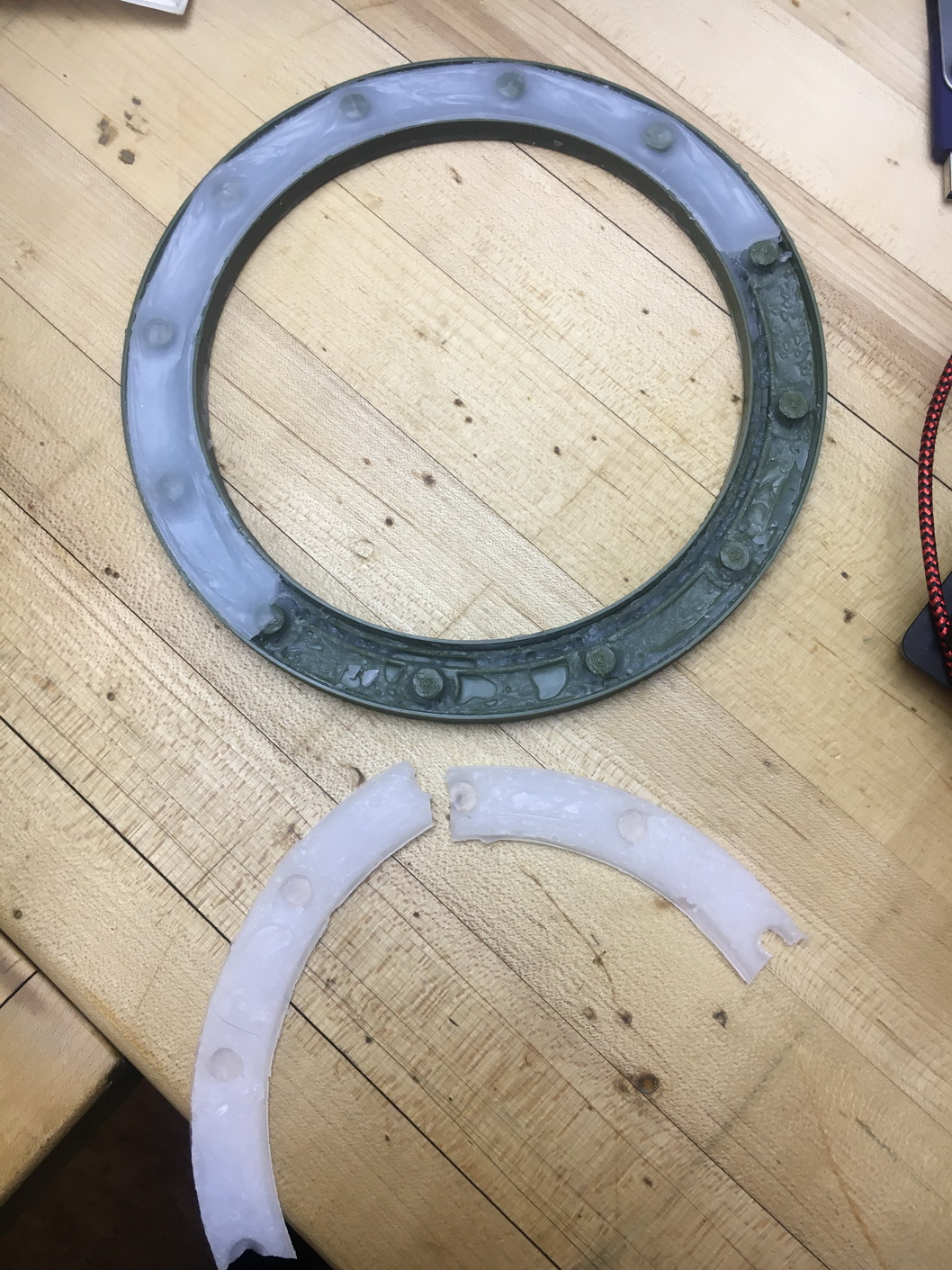
It worked!
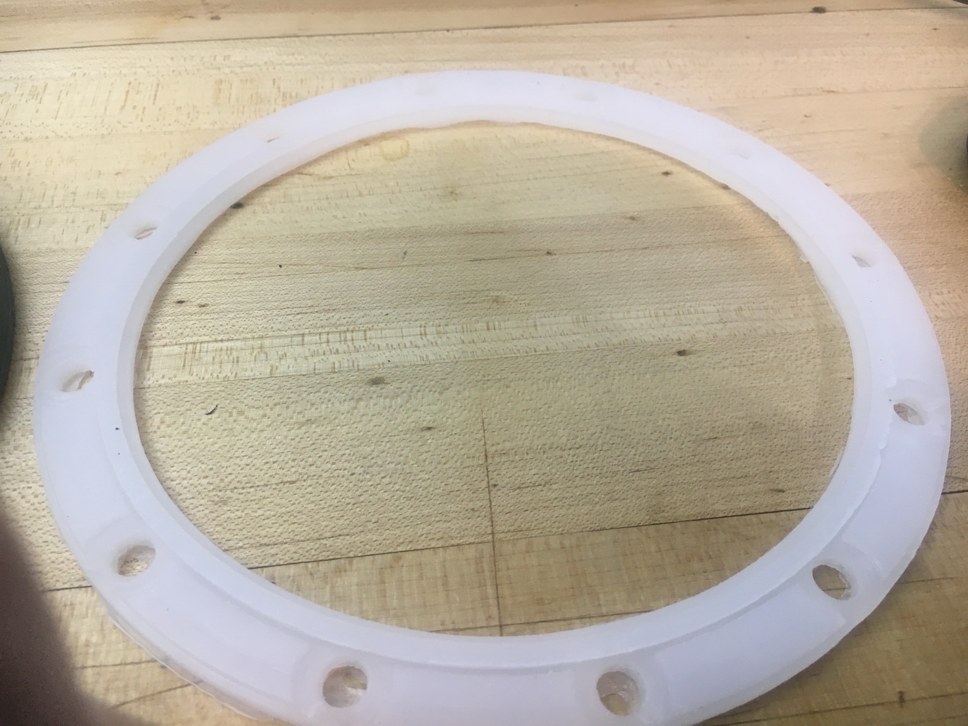
The gasket was a perfect fit.
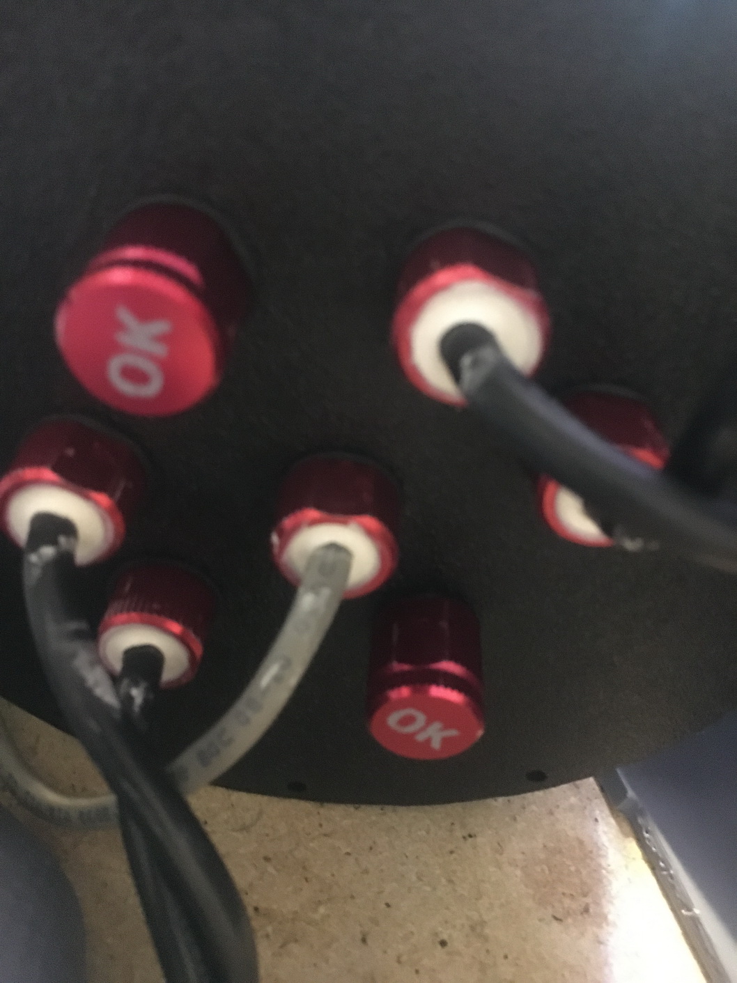
The wire passthroughs for the motor thrusters were sealed using marine epoxy.
Final assembly
Fuctional tests - Passed
Vacuum test - passed
Pool Testing!!
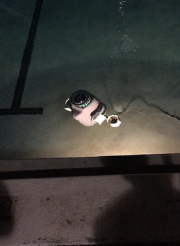
We had some last minute changes to adjust buoyancy and adding a power switch that was accessible without having to dissassemble the outer shell and pull the internal electronics out.
The ROV functioned properly
Some consideration to the motor size would need to be taken.
The flange material would need to be made from a solid plastic to acheive any real depth.
A depth sensor and lights would need to be added as well.